Why Aerospace Forgings Require Precision Forging: Engineering Secrets of Metal Flow Line Integrity and Fatigue Life
8/24/2026
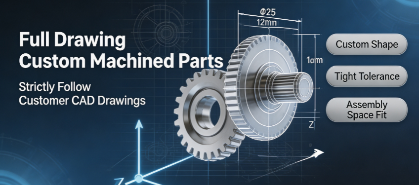
Table of Contents
1. Core Definition Of CAD Drawing Custom Machined Components
2. Three Major Core Advantages Of Full Drawing Custom Machining Service 2.1 100% Strictly Execute Dimensions, Structures And Tolerances From Customer CAD Drawings 2.2 Custom Shape Solves Limited Special Assembly Space Restrictions 2.3 Ultra-Tight Precision Tolerance Control Matches High-End Equipment Matching Standards
3. Complete Custom Machining Production Process Based On Customer CAD Files
4. Material & Surface Treatment Customization Options For Drawing Custom Parts
5. Comparison: Custom Drawing Machined Parts VS Standard Off-The-Shelf Hardware
6. Industry FAQ For Automation, New Energy, Medical & Mold Equipment Purchasers
1. Core Definition Of CAD Drawing Custom Machined Components
Full drawing custom machined parts refer to non-standard mechanical components completely produced according to customers’ 2D/3D CAD engineering drawings, without relying on fixed standard mold sizes or universal part specs. Many automation, new energy and medical equipment adopt exclusive structural designs. Ready-made standard screws, pins, blocks and brackets cannot fit unique internal assembly space or strict precision tolerance limits. General mass-produced standard hardware only follows unified national size standards, unable to adjust shoulder thickness, cavity depth, thread position, outer contour and positioning tolerance for exclusive equipment. Our full drawing custom machining service fully restores every detail on customer CAD drawings, flexibly customizes part outline to fit narrow, irregular or closed assembly spaces, and precisely controls micron-level tolerance to satisfy high-precision equipment assembly demand.
2. Three Major Core Advantages Of Full Drawing Custom Machining Service
2.1 100% Strictly Execute Dimensions, Structures And Tolerances From Customer CAD Drawings
Every machining procedure is programmed directly based on customer original CAD data, no arbitrary simplification or size modification without client confirmation. Engineers carry out drawing review before production: check dimension chain interference, tolerance matching and process feasibility, feed back unreasonable design points to customers for optimization in advance. All features including positioning shoulders, micro grooves, special thread forms, chamfers, anti-loose tooth structures and stepped outer diameters are machined strictly as drawn. Finished products pass full dimensional inspection with three-coordinate measuring instrument to ensure every tolerance band on CAD drawing is fully covered, no out-of-tolerance hidden defects.
2.2 Custom Shape Solves Limited Special Assembly Space Restrictions
Standard parts have fixed outer diameter, head height and overall length, which often collide with internal wiring, cooling pipelines, cylinder frames and sensor bases inside compact equipment. Custom machined parts adjust any contour feature according to actual assembly space: reduce head thickness, add avoidance grooves, shorten overhang sections, design irregular curved outlines or multi-step limit shoulders. One-piece integrated custom structure can combine positioning pin, limit block and connecting screw into a single component, reducing total part count and simplify assembly layout in narrow equipment cavities. Perfect fit eliminates secondary modification of equipment housing, mounting frame or internal brackets after part installation, saving assembly labor and rework cost.
2.3 Ultra-Tight Precision Tolerance Control Matches High-End Equipment Matching Standards
For medical instruments, new energy power equipment, aerospace small components and precision mold accessories, CAD drawings usually mark micron-level tight tolerance requirements on key matching surfaces. Standard off-the-shelf hardware has loose general tolerance, which leads to clearance looseness, axial sliding or assembly jamming after long-term vibration operation. Custom CNC machining controls key feature tolerance down to ±0.003mm via high-rigidity machining centers and stable fixture positioning. Tolerance parameters can be customized separately according to drawing requirements: loose tolerance for non-matching appearance surfaces, ultra-precise tolerance for positioning, thread and sealing mating surfaces, balance production efficiency and assembly precision.
3. Complete Custom Machining Production Process Based On Customer CAD Files
1. CAD drawing receiving & technical review: Verify dimension, tolerance, material demand and surface treatment requirement, communicate ambiguous structure details with clients.
2. Process programming & fixture customizing: Generate CNC machining program from CAD model, design dedicated positioning fixture to avoid clamping deformation.
3. Raw material cutting: Select matching metal blank per drawing material standard (aluminum alloy, stainless steel, alloy steel, brass, plastic etc.).
4. Multi-axis CNC precision machining: Turning, milling, drilling, tapping, slotting, chamfering complete all contour features on drawing.
5. Deburring & surface treatment: Passivation, anodizing, electroplating, hardening, sandblasting as customer custom requirements.
6. Full precision inspection: Use caliper, micrometer, three-coordinate detector to test all tolerance dimensions on CAD drawing, issue inspection report.
7. Neutral packaging & delivery: Anti-rust packaging, attach dimension test data sheet together with finished custom parts.
4. Material & Surface Treatment Customization Options For Drawing Custom Parts
Optional Raw Materials
304 / 316 stainless steel, 6061 / 7075 aluminum alloy, 45# / 40Cr alloy steel, brass, copper, POM, PA66 engineering plastic, titanium alloy for lightweight aerospace parts.
Optional Custom Surface Finishes
Passivation, zinc plating, nickel plating, hard anodizing, conductive anodizing, black oxide, sandblasting, polishing, quenching & tempering heat treatment, multi-layer anti-corrosion coating for salt fog resistant workshop.
5. Comparison: Custom Drawing Machined Parts VS Standard Off-The-Shelf Hardware
表格
Evaluation Index | Full Drawing Custom Machined Parts Per Customer CAD | Ordinary Ready-Made Standard Hardware | Equipment Assembly Practical Impact |
Structure & Dimension Matching | 1:1 restore CAD drawing, fully fit exclusive assembly space | Fixed unified size, easy internal interference | Standard parts require frame cutting & modification |
Precision Tolerance Control | Custom micron tight tolerance for key mating positions | Wide general tolerance range | Standard parts cause vibration looseness or jamming |
Multi-Function Integrated Design | Combine multiple part functions into one single component | Single independent function per piece | Standard hardware increase assembly steps & spare part types |
Material & Surface Treatment | Fully customized per drawing application environment | Limited fixed material & single plating | Standard parts fail corrosion, lightweight or high-temp working test |
Drawing Traceability | Each batch match original CAD file, complete inspection data | Unified mass production without custom drawing record | Difficult to adjust size when equipment design updated |
6. Industry FAQ For Automation, New Energy, Medical & Mold Equipment Purchasers
Q1: What format of CAD drawing files can be accepted for custom machining production? A1. We support DWG, DXF, STEP, IGES, SolidWorks SLDPRT and other mainstream 2D/3D CAD formats; customers can send complete drawing packages with tolerance marking directly. Q2: If there are unreasonable structural or tolerance designs on customer CAD drawings, will the factory process parts directly? A2. No. Professional engineers will sort out design risks in drawing review stage and send optimization suggestions to customers for confirmation before formal machining, to avoid mass unqualified finished parts. Q3: Can custom machined parts simultaneously solve narrow assembly space and ultra-precision tolerance requirements at the same time? A3. Yes. CNC multi-axis machining can customize special avoidance contours to adapt limited space, while high-rigidity equipment controls micron-level tight tolerance on key mating surfaces to meet both demands. Q4: For small batch prototype test and mass formal production, does the factory keep the original customer CAD drawing data for repeat orders? A4. Customer CAD files are filed independently confidentially. Repeat orders can directly call drawing data without secondary drawing review, shorten reorder delivery cycle greatly.